GitHub
Get the tutorial project from GitHub - It contains all the assets necessary to achieve the final result!
The fog of war effect in Civilization VI is a perfect example for a simple compute shader setup. If you always wanted to learn about the basics of those, this tutorial is for you.
Compared to the previous case studies, this one is a bit shorter and probably easier. You should be able to follow it even without prior shader or C# programming skills by following the step-by-step guide, more experienced developers can skip some of the basics.
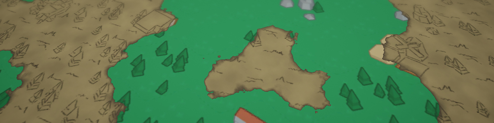
As usual, let’s start our project by looking at the effect in-game and analyse it. Luckily, Civilization is turn based and we can look at the effect for as long as we like. I loaded up an older save of mine and took a couple of screenshots of various locations in the world.
The first thing we are looking at is the edge between visible and hidden area. The "hidden" area here is the fog of war, the hand drawn, map like area. You can clearly see that the edge doesn’t strictly follow the hex fields underneath and that there is some noise present, most likely perlin noise.
Perlin noise is a type of noise used for modelling organic shapes. Typical textures based on it are terrain height maps and dissolve effects.
Let’s focus on the visuals of the hidden area next. The effect here appears to be an image effect over the static meshes (buildings, vegetation, …) in the scene (edge outline and some shadow-like visuals). The dynamic objects are obviously not visible, as this would defeat the purpose of a fog of war.
In addition to that, there are some hand drawn textures for the terrain, like the grass that is especially visible on empty tiles. In our project we will rely only on those textures, as creating an image effect like this in addition to the rest of the shaders would be way too much for a single tutorial.
Lastly, we have two more things that make up the effect of the fog of war. The first one is a gradient at the edge of the area, you can clearly see it on the ocean tiles. You can also see that it doesn’t have a constant thickness, indicating that it is also based on the previously mentioned perlin noise.
Second, we have some slight noise on the effect to break up the monotony on large, empty tiles. You can see this on the ocean tiles in the south (those without the shore waves on it). We can use our perlin noise texture for this as well.
As usual, there is a template project for this tutorial with a lot of the setup already done. If you haven’t already, you can clone or download it from GitHub.
Template ProjectIn the next chapter we’ll quickly go through the important parts of the setup, especially the compute shader dispatcher C# script.
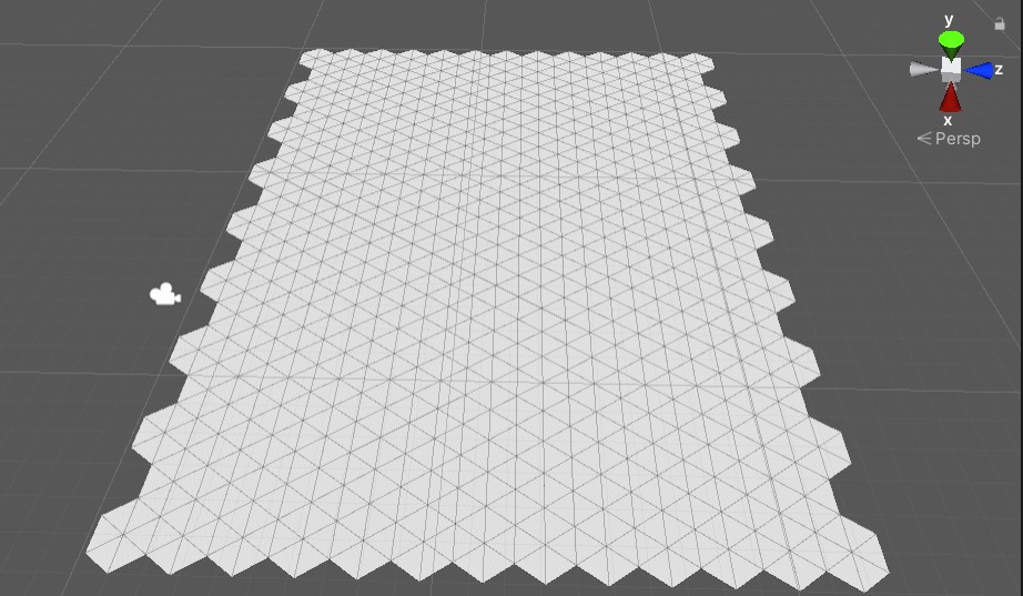
Start by opening “Assets/SampleScene.unity”. As you can see, there isn’t a lot of stuff here, only a simple hex grid, the directional light and the camera.
Two things that I want to highlight here are the post-processing setup on the camera and the material setup.
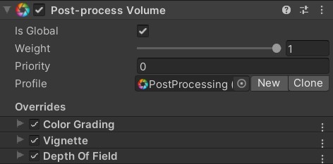
If you select the main camera, you can see the post-processing volume and layer. We are using Unity’s post-processing package here. The effects that are currently on here are quite simple. There is some neutral tonemapping, a slight vignette and depth of field. You can freely experiment with those effects and add additional ones if you want to change the look of the result.
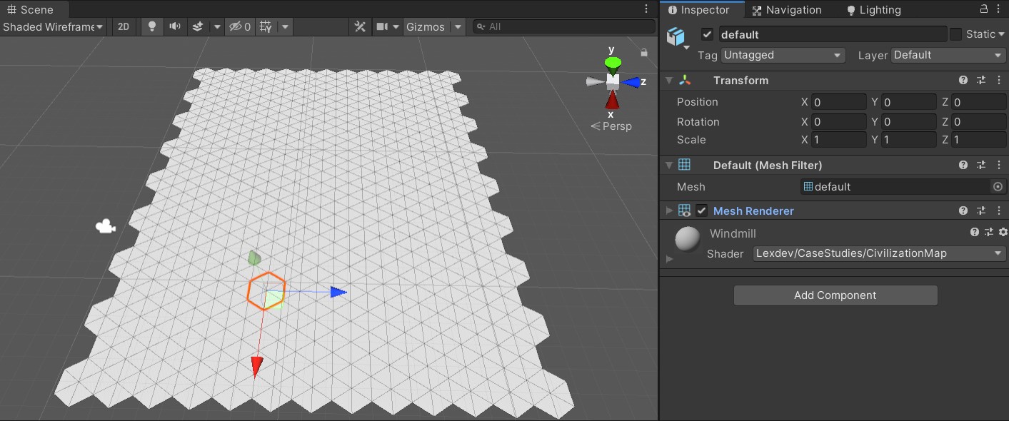
If you select a random hex field in the scene, you can see that it already has a material assigned to it. While they are all using the same shader, they are using different sprites depending on the tile. In the case of the image above, the tile will be a windmill later. There are 9 different tiles in the project, you can find their materials in the “Assets/Materials” folder.
This leads us to the tile textures. If you open the “Assets/Textures” folder, you can find the colour textures for each tile, as well as the hand drawn version of them with the suffix “_Map”. The colour textures are part of the Hexagon Pack from Kenney.
Kenney.nl has a lot of free assets (2D, 3D and Audio) you can use in your projects. Most of them are even CC licensed.
The hand drawn versions of those textures are congruent to the colour textures, which is important for the effect not to have any offset to the original tile at the edge of the fog of war.
There are two more textures in this folder. “PerlinNoise” is, well, a perlin noise texture.
I used this online texture generator by Christian Petry for the perlin noise texture. If you want to experiment with other noise values, you can simply replace the texture in the project with a new one.
The second texture (“MapBackground”) is used for the spots on the fog of war that break up the monotony on large, empty surfaces.
With the textures out of the way, let’s focus on the shaders and scripts. There are two shaders in the “Assets/Shaders” folder, “MaskCompute” is the compute shader used for generating a mask with the visibly and hidden areas, “Tile Shader” is the shader that is used on the tile materials. It samples the value in the mask texture created by the compute shader and renders the tile texture or the fog of war based on it. We’ll talk about the shaders in more detail in the next chapters.
Lastly, there are the two scripts located in “Assets/Scripts”. In order to understand what is going on in the shaders, it is important to understand the C# logic as well. Let’s go through both step by step, starting with “GridCell”.
This script can be found on every single hex cell in the scene. Its purpose is to control the visibility of the cell and toggle it when there’s a mouse interaction.
private void Start()
{
    MaskRenderer.RegisterCell(this);
}
At the start, each cell adds itself to the list of cells in the “MaskRenderer” script by calling the “RegisterCell” function. In a full game this list should simply be filled using the inspector, however it is quite useful to have a function like this for prototyping, as you can easily increase the size of the map without further setup.
private void OnMouseDown()
{
    ToggleVisibility();
}

private void OnMouseEnter()
{
    ToggleVisibility();
}
We want to be able to interact with the demo and toggle the visibility of the cells. For this, every cell has a collider on it. By using OnMouseDown() and OnMouseEnter() we can drag our mouse over the screen and can toggle every cell’s visibility along the way.
private IEnumerator AnimateVisibility(float targetVal)
{
    float startingTime = Time.time;
    float startingVal = Visibility;
    float lerpVal = 0.0f;
    while(lerpVal < 1.0f)
    {
        lerpVal = (Time.time - startingTime) / 1.0f;
        Visibility = Mathf.Lerp(startingVal, targetVal, lerpVal);
        yield return null;
    }
    Visibility = targetVal;
}
Let’s talk about this coroutine here for a second. The pattern you can see here is typical for an animation that is controlled by a C# script. The advantage of doing the calculations ourselves instead of preparing an animation in unity and playing it is that we can stop the animation and any point.
Open the “MaskRenderer.cs” script next. It is important that you fully understand it, as it controls the logic of the compute shader.
private static List<GridCell> cells;

public static void RegisterCell(GridCell cell)
{
        cells.Add(cell);
}
As mentioned before, each cell adds itself to the list of cells used by the mask renderer. We create a compute buffer with a shader friendly variable struct from the list later.
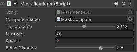
[SerializeField, Range(64, 4096)]
private int TextureSize = 1024;

[SerializeField]
private float MapSize = 0;

[SerializeField]
private float Radius = 1.0f;

[SerializeField, Range(0.0f, 1.0f)]
private float BlendDistance = 0.8f;
There are a bunch of variables exposed to the editor that represent some basic settings for the effect. “TextureSize” is the size of the created mask texture, ideally this is a power of 2. “MapSize” ist the physical size of the hex grid in units. We need this number to be able to map the mask texture onto the grid later. “Radius” ist the radius of a single hex cell, i.e. the distance between the centre and a corner. Instead of determining whether the texel of the texture we are currently calculating is inside a hex field, we instead check whether it is inside a circle around the field. The last one is “BlendDistance”, which determines the width around the visible area that is used for blending with the non-visible one. The inner radius of the blend area around a cell is “Radius”, the outer radius in “Radius” + “BlendDistance”.
private RenderTexture maskTexture;This is the texture we are writing to in the compute shader. There are a lot of things you have to consider when working with render textures, they are quite low level compared to other C# Unity objects. They aren’t being cleaned up for you by the garbage collector like the other objects and you have to specifically call Release() once you no longer need them to make sure the memory they were using is available for other things.
Render texture data lives in GPU memory which means they work well when only using them on the GPU side of things like in our case (we write to them using the compute shader, we read from them in the tile shader). However, as soon as you copy them back to CPU memory, you’ll notice quite a high spike in your frame time.
private static readonly int textureSizeId = Shader.PropertyToID("_TextureSize");
private static readonly int cellCountId = Shader.PropertyToID("_CellCount");
private static readonly int mapSizeId = Shader.PropertyToID("_MapSize");

private static readonly int radiusId = Shader.PropertyToID("_Radius");
private static readonly int blendId = Shader.PropertyToID("_Blend");

private static readonly int maskTextureId = Shader.PropertyToID("_Mask");

private static readonly int cellBufferId = Shader.PropertyToID("_CellBuffer");
There are quite a lot of variables we are setting from this C# script, most of them every frame. In order to avoid string comparisons for every call, we cache the ID of the properties as integers. You should always do this when working with shaders in a C# script. The name of each variable needs to be the same here and in the shaders for Unity to be able to assign them.
private struct CellBufferElement
{
    public float PositionX;
    public float PositionY;
    public float Visibility;
}

private List<CellBufferElement> bufferElements;
private ComputeBuffer buffer = null;
The compute buffer is used to parse the cell information to the compute shader. By having the same type for each of the structs values we can simply use a float3 in our compute shader later to represent each cell’s data. We’ll see how the buffer works later.
private void Awake()
{
    cells = new List();

    maskTexture = new RenderTexture(TextureSize, TextureSize, 0, RenderTextureFormat.ARGB32, RenderTextureReadWrite.Linear)
    {
        enableRandomWrite = true
    };
    maskTexture.Create();

    computeShader.SetInt(textureSizeId, TextureSize);
    computeShader.SetTexture(0, maskTextureId, maskTexture);

    Shader.SetGlobalTexture(maskTextureId, maskTexture);
    Shader.SetGlobalFloat(mapSizeId, MapSize);

    bufferElements = new List();
}
We are doing the basic setup of the shaders and the render texture in here. Note that while the texture format we are using here is strictly speaking overkill and could be swapped for another one (we could get away with a single channel format since we only need one for the mask value), it is essential that we have random write enabled. We are setting the texture size and the texture itself for the compute shader and as global variables.
You should never use global shader variables in a large-scale project. However, they are quite useful for prototyping as those variables can be used in any shader without further setup.
private void OnDestroy()
{
    buffer?.Dispose();
    maskTexture?.Release();
}
As mentioned earlier, there are some lower level Unity objects for which we must manage memory ourselves. In our case that is the compute buffer and the render texture.
bufferElements.Clear();
foreach (GridCell cell in cells)
{
    CellBufferElement element = new CellBufferElement
    {
        PositionX = cell.transform.position.x,
        PositionY = cell.transform.position.z,
        Visibility = cell.Visibility
    };

    bufferElements.Add(element);
}
The last thing in our script is the Update() function. In it, we start by creating compute buffer elements for each cell and adding them to our list of elements. We must update those each frame because our visibility values change depending on whether a cell should be visible or not.
if(buffer == null)
    buffer = new ComputeBuffer(bufferElements.Count * 3, sizeof(float));
If we don’t have a compute buffer (this happens only in the first frame), we are creating a new one. The first parameter of the constructor is the number of elements in total, in our case the number of cells multiplied with 3 elements per cell, the second parameter is the size of each element (i.e. the amount of bytes each element has). The easiest way to figure out the size is the sizeof operator, which gives us the size of the type we pass to it.
buffer.SetData(bufferElements);
computeShader.SetBuffer(0, cellBufferId, buffer);

computeShader.SetInt(cellCountId, bufferElements.Count);
computeShader.SetFloat(radiusId, Radius / MapSize);
computeShader.SetFloat(blendId, BlendDistance / MapSize);
This part should be mostly self-explanatory, as we are simply setting the values of all the variables which we are needing in our compute shader. Two things are worth mentioning here. The first one is the 0 we pass to the SetBuffer() function, which indicates the index of the compute kernel we are setting the buffer for. We only have one, thus our index is 0. Second, we are dividing the radius and the blend distance by the physical map size. We must make sure all of our lengths are the same scale, when working with textures the easiest scale is UV scale [0;1].
computeShader.Dispatch(0, Mathf.CeilToInt(TextureSize / 8.0f), Mathf.CeilToInt(TextureSize / 8.0f), 1);The dispatch function executes the actual compute kernel. The first parameter is once more the kernel index which is 0 in our case. The other three parameters are the thread group count in x, y and z direction. By now you might be quite confused so let’s talk a bit about how compute shaders run on the GPU.
GPU are built to execute the same instructions on multiple data in parallel, e.g. if we have a function in a vertex shader “x += 1”, we are adding 1 to x for a bunch of vertices in parallel. The data doesn’t have to be vertices, it could also be pixels or, in the case of a compute shader, basically anything. The size of those groups can be set by us in the compute shader, in our case I set them to 8x8x1. You can imagine this as our compute shader rendering 8x8 texels of our texture at once.
When dispatching the compute shader, it is therefore important to calculate how often we must dispatch it in x, y and z direction to cover the whole render texture. Since we are working in 2D we can ignore z and set it to one. We can calculate the amount of thread groups in x and y direction by dividing our texture resolution by 8, the size of each group.
If we have a texture the size of 512 by 512, we would therefore dispatch the compute kernel (512/8) x (512/8) = 64 x 64 = 4096 times. There will be a future tutorial where we go into more details, but for now this should give you a simple introduction into the topic. Let’s start writing our shaders.
Open the “Assets/Shaders/MaskCompute.compute“ shader, you should see a bare-bone structure I prepared.
#pragma kernel CSMain

[numthreads(8,8,1)]
void CSMain (uint3 id : SV_DispatchThreadID)
{

}
The first line tells Unity the name of our compute kernel, we only have one so that part is straight forward. The second line tells Unity the size of our thread group, in our case 8x8x1. I discussed the basics of thread groups in the last chapter. The last thing here is the id parameter we are parsing to the function. This variable stores the id of the thread we are currently working on, again in 3 dimensions. In our case id.xy is the pixel the current thread is calculating the value for.
Start by adding the basic variables from our C# script. There shouldn’t be any surprises here, remember that radius and blend distance are already in UV scale.
+   int _CellCount;
+   int _TextureSize;
+   float _MapSize;
+   float _Radius;
+   float _Blend;
Another variable we need is for the compute buffer that contains all the cell data. Remember how each element in the buffer contains 3 float values? The size of our buffer therefore is "3 * cellCount", and the data inside the buffer looks like this: "cell0.posX | cell0.posY | cell0.visibility | cell1.posX | cell1.posY | cell1.visibility | ...". We have to remember this when accessing the buffer later.
+ StructuredBuffer<float> _CellBuffer;The last variable we need is our mask texture. Since we need to write to it, the type must be read/write enabled, thus RWTexture2D. Each pixel in the texture is of type float4, thus we have one float per channel.
+ RWTexture2D<float4> _Mask;We can now code our actual compute function. Let’s start by setting the value of our current texel to 0.
[numthreads(8,8,1)]
void CSMain (uint3 id : SV_DispatchThreadID)
{
+   _Mask[id.xy] = float4(0, 0, 0, 1);
}
We must loop through all the cells and determine whether the cell is in range of the texel and visible. If it is, we set the mask value to 1, if not we leave it at 0. We can use a simple for loop for this.
[numthreads(8,8,1)]
void CSMain (uint3 id : SV_DispatchThreadID)
{
    _Mask[id.xy] = float4(0, 0, 0, 1);
+   for (int i = 0; i < _CellCount; i++)
+   {
+
+   }
}
In order to calculate the distance between the current texel and each cell, we need both positions in the same space. Earlier we started converting values to UV space, let’s do this for the texel position and the cell centre as well. We now run into the issue of the data alignment in our structured buffer. If we want to access the x position of the cell, we have to access the value at 3 * cellIndex, for the y position it's 3 * cellIndex + 1.
[numthreads(8,8,1)]
void CSMain (uint3 id : SV_DispatchThreadID)
{
    _Mask[id.xy] = float4(0, 0, 0, 1);
    for (int i = 0; i < _CellCount; i++)
    {
+       float2 UVPos = id.xy / (float)_TextureSize;
+       float2 centerUVPos = float2(_CellBuffer[3 * i], _CellBuffer[3 * i + 1]) / _MapSize;
    }
}
We can now calculate the distance between the two by simply using length().
[numthreads(8,8,1)]
void CSMain (uint3 id : SV_DispatchThreadID)
{
    _Mask[id.xy] = float4(0, 0, 0, 1);
    for (int i = 0; i < _CellCount; i++)
    {
        float2 UVPos = id.xy / (float)_TextureSize;
        float2 centerUVPos = float2(_CellBuffer[3 * i], _CellBuffer[3 * i + 1]) / _MapSize;
+       float UVDistance = length(UVPos - centerUVPos);
    }
}
All that’s left to do now is to calculate, whether the distance is smaller than the radius and change the mask value to 1 if it is. Since we want a smooth blend at the edge based on the blend distance variable, we can use smoothstep to achieve that. We must make sure to multiply this value with the visibility of the cell to render only visible cells to the mask.
[numthreads(8,8,1)]
void CSMain (uint3 id : SV_DispatchThreadID)
{
    _Mask[id.xy] = float4(0, 0, 0, 1);
    for (int i = 0; i < _CellCount; i++)
    {
        float2 UVPos = id.xy / (float)_TextureSize;
        float2 centerUVPos = float2(_CellBuffer[3 * i], _CellBuffer[3 * i + 1]) / _MapSize;
        float UVDistance = length(UVPos - centerUVPos);

+       float val = smoothstep(_Radius + _Blend, _Radius, UVDistance) * _CellBuffer[3 * i + 2];
    }
}
Smoothstep works as follows: If the “UVDistance” variable is larger than “_Radius + _Blend”, it returns 0. If it’s smaller than “_Radius”, it returns 1. In between those values it smoothly interpolates between 0 and 1.
There is one more thing to consider. Our cells inside the buffer aren’t in a specific order, therefore a texel could be inside the radius of a visible cell and the mask value thus 1, only to have it’s mask value changed to 0 later in the loop because the texel is not inside the radius of the next cell. We can fix this by making sure the mask value is only written if it’s larger than the existing one.
[numthreads(8,8,1)]
void CSMain (uint3 id : SV_DispatchThreadID)
{
    _Mask[id.xy] = float4(0, 0, 0, 1);
    for (int i = 0; i < _CellCount; i++)
    {
        float2 UVPos = id.xy / (float)_TextureSize;
        float2 centerUVPos = float2(_CellBuffer[3 * i], _CellBuffer[3 * i + 1]) / _MapSize;
        float UVDistance = length(UVPos - centerUVPos);

        float val = smoothstep(_Radius + _Blend, _Radius, UVDistance) * _CellBuffer[3 * i + 2];
+       val = max(_Mask[id.xy].r, val);
    }
}
Once we assign the mask value, we are good to go. Easy, right?
[numthreads(8,8,1)]
void CSMain (uint3 id : SV_DispatchThreadID)
{
    _Mask[id.xy] = float4(0, 0, 0, 1);
    for (int i = 0; i < _CellCount; i++)
    {
        float2 UVPos = id.xy / (float)_TextureSize;
        float2 centerUVPos = float2(_CellBuffer[3 * i], _CellBuffer[3 * i + 1]) / _MapSize;
        float UVDistance = length(UVPos - centerUVPos);

        float val = smoothstep(_Radius + _Blend, _Radius, UVDistance) * _CellBuffer[3 * i + 2];
        val = max(_Mask[id.xy].r, val);

+       _Mask[id.xy] = float4(val, val, val, 1);
    }
}
Let’s open the “Assets/Shaders/TileShader.shader” and quickly adjust it to display the mask. The shader is a basic surface shader framework, there is nothing special to it. We discussed the basic surface shader setup in more detail in the previous tutorial about the Gears Hammer of Dawn.
struct Input
{
+   float3 worldPos;
};

+ float _MapSize;
+ sampler2D _Mask;

void surf (Input IN, inout SurfaceOutputStandard o)
{
+   o.Albedo = tex2D(_Mask, IN.worldPos.xz / _MapSize).rgb;
}
In order to map the mask texture properly onto the grid, we need the world position of the vertex. In surface shaders, we can get it by adding the “worldPos” variable to the input struct. We also need the “_MapSize” variable and our “_Mask” texture in order to scale the world position and sample the texture at the calculated coordinates. Remember how we used Global shader variable for those? Their value should be set automatically by our C# script. We can now sample the texture and assign the mask colour to the surface output struct’s albedo colour.
Once we have the shader modified, we can go into play mode and click on the grid to see how the mask changes its value.
With the mask out of the way, we can focus on the tile shader next.
We start by adding a lot of properties to our shader, let’s go through each of them and discuss what they are being used for.
Properties
{
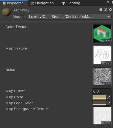
+ [NoScaleOffset] _MainTex("Color Texture", 2D) = "white" {}
+ [NoScaleOffset]_MapTex("Map Texture", 2D) = "white" {}
+ [NoScaleOffset]_Noise("Noise", 2D) = "black" {}
+ _Cutoff("Map Cutoff", float) = 0.4
+ _MapColor("Map Color", Color) = (1,1,1,1)
+ _MapEdgeColor("Map Edge Color", Color) = (1,1,1,1)
+ [NoScaleOffset]_MapBackground("Map Background Texture", 2D) = "white" {}
}“_MainTex” is the texture containing the colour image of the tile, “_MapTex” is the hand-drawn version of it. “_Noise” is the perlin noise texture we are using for the edge of the fog of war. The “_Cutoff” value determines at which mask value we are switching from the colour tile to the fog of war visuals, we want this to be a hard cut. “_MapColor” is the basic colour of the fog of war map, usually light brown, while “_MapEdgeColor” is the colour the effect has towards the edges. Lastly, “_MapBackground” is the slight background texture we are laying on top of the fog of war effect to give it some more variation.
We need UV coordinates for sampling “_MainTex” and “_MapTex”. We can get those by adding float2 variables with the prefix “uv” to the input struct.
struct Input
{
    float3 worldPos;
+   float2 uv_MainTex;
+   float2 uv_MapTex;
};
Since properties are Unity constructs used for exposing variables to the inspector, we need to add the actual variables with the same name to the CG shader code part of the file.
float _MapSize;
sampler2D _Mask;

+ sampler2D _MainTex;
+ sampler2D _MapTex;

+ sampler2D _Noise;

+ float _Cutoff;

+ float4 _MapColor;
+ float4 _MapEdgeColor;
+ sampler2D _MapBackground;
We can now start working on the surface function itself. The first thing we are doing is sampling the two tile textures. While we are at it, let's store the mask value in its own variable.
void surf (Input IN, inout SurfaceOutputStandard o)
{
+   float4 maskVal = tex2D(_Mask, IN.worldPos.xz / _MapSize);
+   float4 tile = tex2D(_MainTex, IN.uv_MainTex);
+   float4 tileMap = tex2D(_MapTex, IN.uv_MapTex);

+   o.Albedo = mask.rgb;
}
We also need to sample the map background texture and the noise texture.
void surf (Input IN, inout SurfaceOutputStandard o)
{
    float4 maskVal = tex2D(_Mask, IN.worldPos.xz / _MapSize);
    float4 tile = tex2D(_MainTex, IN.uv_MainTex);
    float4 tileMap = tex2D(_MapTex, IN.uv_MapTex);
+   float4 mapBackground = tex2D(_MapBackground, IN.worldPos.xz / _MapSize);
+   float noise = tex2D(_Noise, IN.worldPos.xz / _MapSize).r;

    o.Albedo = mask.rgb;
}
Using our current mask as is would result in some quite monotone edges in the shape of circles around the visible area, which would look quite bad. We want the edge to be noisier, in order to do that we can subtract the noise value from the mask value. To avoid weird and undefined behaviour later, make sure to clamp the result between 0 and 1.
void surf (Input IN, inout SurfaceOutputStandard o)
{
    float4 maskVal = tex2D(_Mask, IN.worldPos.xz / _MapSize);
    float4 tile = tex2D(_MainTex, IN.uv_MainTex);
    float4 tileMap = tex2D(_MapTex, IN.uv_MapTex);
    float4 mapBackground = tex2D(_MapBackground, IN.worldPos.xz / _MapSize);
    float noise = tex2D(_Noise, IN.worldPos.xz / _MapSize).r;

+   float maskNoise = clamp(maskVal - noise, 0, 1);

    o.Albedo = mask.rgb;
}
There is an issue with this function though. The noise value can be anything in between 0 and 1, so it might subtract 1 from the mask in an area where the tile should be visible, resulting in spots that are being rendered as fog of war even though they shouldn’t. We can fix this by multiplying the noise with the inverse of the mask value.
void surf (Input IN, inout SurfaceOutputStandard o)
{
    float4 maskVal = tex2D(_Mask, IN.worldPos.xz / _MapSize);
    float4 tile = tex2D(_MainTex, IN.uv_MainTex);
    float4 tileMap = tex2D(_MapTex, IN.uv_MapTex);
    float4 mapBackground = tex2D(_MapBackground, IN.worldPos.xz / _MapSize);
    float noise = tex2D(_Noise, IN.worldPos.xz / _MapSize).r;

+   float maskNoise = clamp(maskVal - (1.0f - maskVal) * noise, 0, 1);

    o.Albedo = mask.rgb;
}
While experimenting, I realized that the noise effect now is not as visible in the whole blended area as it should be, since it currently has less impact the closer we are to the cell’s radius. By adding a power function, we can increase the impact of the noise throughout the blended area.
void surf (Input IN, inout SurfaceOutputStandard o)
{
    float4 maskVal = tex2D(_Mask, IN.worldPos.xz / _MapSize);
    float4 tile = tex2D(_MainTex, IN.uv_MainTex);
    float4 tileMap = tex2D(_MapTex, IN.uv_MapTex);
    float4 mapBackground = tex2D(_MapBackground, IN.worldPos.xz / _MapSize);
    float noise = tex2D(_Noise, IN.worldPos.xz / _MapSize).r;

+   float maskNoise = clamp(maskVal - pow(1.0f - maskVal, 0.01f) * noise, 0, 1);

    o.Albedo = mask.rgb;
}
We can now check whether this adapted noise value is smaller than the specified “_Cutoff” value, and if it is, render the fog of war. The fog of war visuals are a combination of the “_MapColor”, the hand drawn tile and the background texture.
void surf (Input IN, inout SurfaceOutputStandard o)
{
    float4 maskVal = tex2D(_Mask, IN.worldPos.xz / _MapSize);
    float4 tile = tex2D(_MainTex, IN.uv_MainTex);
    float4 tileMap = tex2D(_MapTex, IN.uv_MapTex);
    float4 mapBackground = tex2D(_MapBackground, IN.worldPos.xz / _MapSize);
    float noise = tex2D(_Noise, IN.worldPos.xz / _MapSize).r;

    float maskNoise = clamp(maskVal - pow(1.0f - maskVal, 0.01f) * noise, 0, 1);

+   if(maskNoise < _Cutoff)
+       tile = _MapColor * tileMap * mapBackground;

+   o.Albedo = tile.rgb;
}Since we want the edge to be a darker colour, we can add a simple lerp to the fog of war colour based on the adapted mask value.
void surf (Input IN, inout SurfaceOutputStandard o)
{
    float4 maskVal = tex2D(_Mask, IN.worldPos.xz / _MapSize);
    float4 tile = tex2D(_MainTex, IN.uv_MainTex);
    float4 tileMap = tex2D(_MapTex, IN.uv_MapTex);
    float4 mapBackground = tex2D(_MapBackground, IN.worldPos.xz / _MapSize);
    float noise = tex2D(_Noise, IN.worldPos.xz / _MapSize).r;

    float maskNoise = clamp(maskVal - pow(1.0f - maskVal, 0.01f) * noise, 0, 1);

    if(maskNoise < _Cutoff)
+       tile = lerp(_MapColor * tileMap * mapBackground, _MapEdgeColor, maskNoise / _Cutoff);

    o.Albedo = tile.rgb;
}
And with that the code is done! I’ll quickly go over the material settings in the next chapter.
All the materials are setup the same way, only the colour and map textures are different. In my examples, I am using a cutoff value of 0.3, the map colour in my case is #BCA76E, the edge colour #574A36.
If you haven’t changed the map, the size should be 26, I am using a radius of 1.0 and a blend distance of 0.8.
Another one done! This one was finally a bit shorter than the previous ones (still 4000 words though), nonetheless you should feel great for working through all of it. If you had any issues along the way, make sure to check out the final version of the project.
Final ProjectMake sure to share your work with me on Twitter or the community Discord, if you enjoyed this tutorial consider supporting me on Patreon. You can also use twitter to send me questions and suggest future topics. Happy shading!
Get the tutorial project from GitHub - It contains all the assets necessary to achieve the final result!
Help me to create more amazing tutorials like this one by supporting me on Patreon!
Make sure to follow me on Twitter to be notified whenever a new tutorial is available.
If you have questions, want to leave some feedback or just want to chat, head over to the discord server! See you there!
Projects on this page are licensed under the MIT license. Check the included license files for details.

If you like the tutorials and want to support me, head over to Patreon to do so! You'll also get access to some amazing perks like special discord roles with priority support!
I'd like to get in touch and read what you think about the site.
Feedback is always appreciated!
Feel free to send me suggestions for future tutorials.
Questions and messages from patrons will be answered with a higher priority!